


Top Sellers
Top 3 Entry-Level Underwater Camera Systems

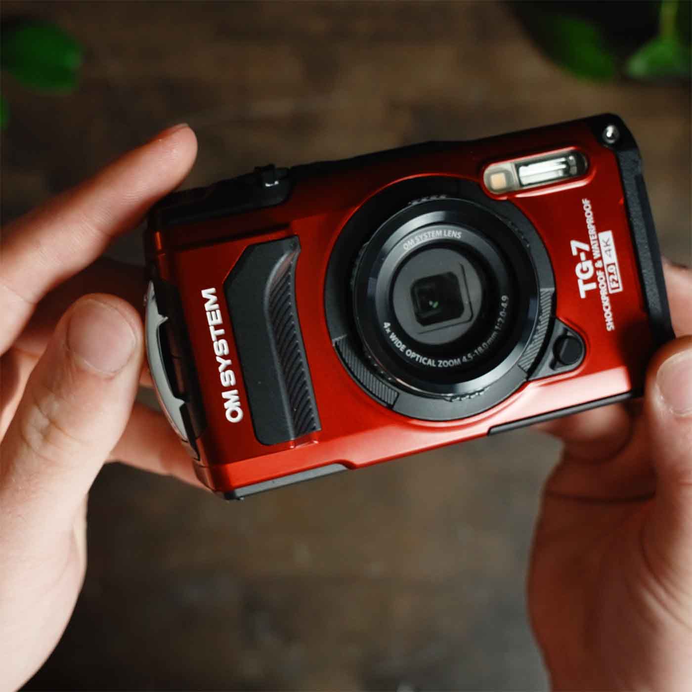
Best Macro
If you love the small stuff then you can't do better than the petite (and waterproof) OM System Tough TG-7.
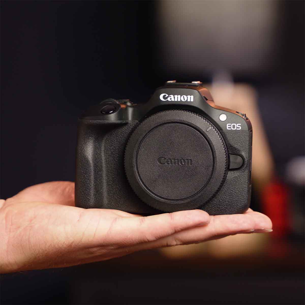
Best Compact
If you want to shoot a compact system without sacrificing performance or image quality then bet on the Canon EOS R100.
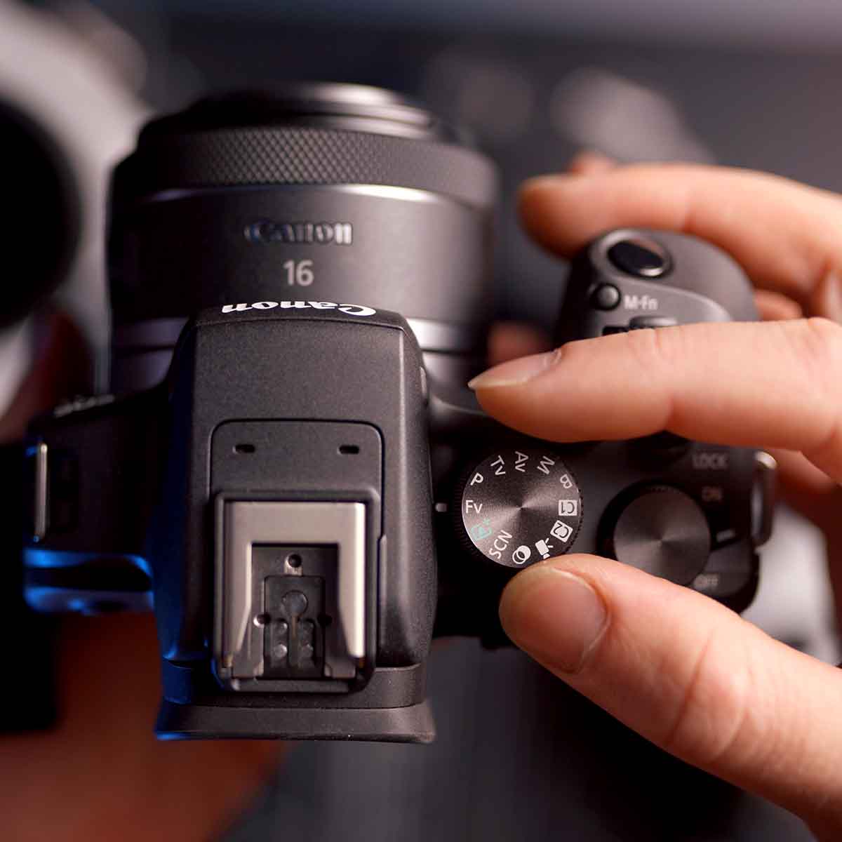
Best Value
If you want cutting edge technology without the destroying your budget then the Canon EOS R10 is the clear leader.
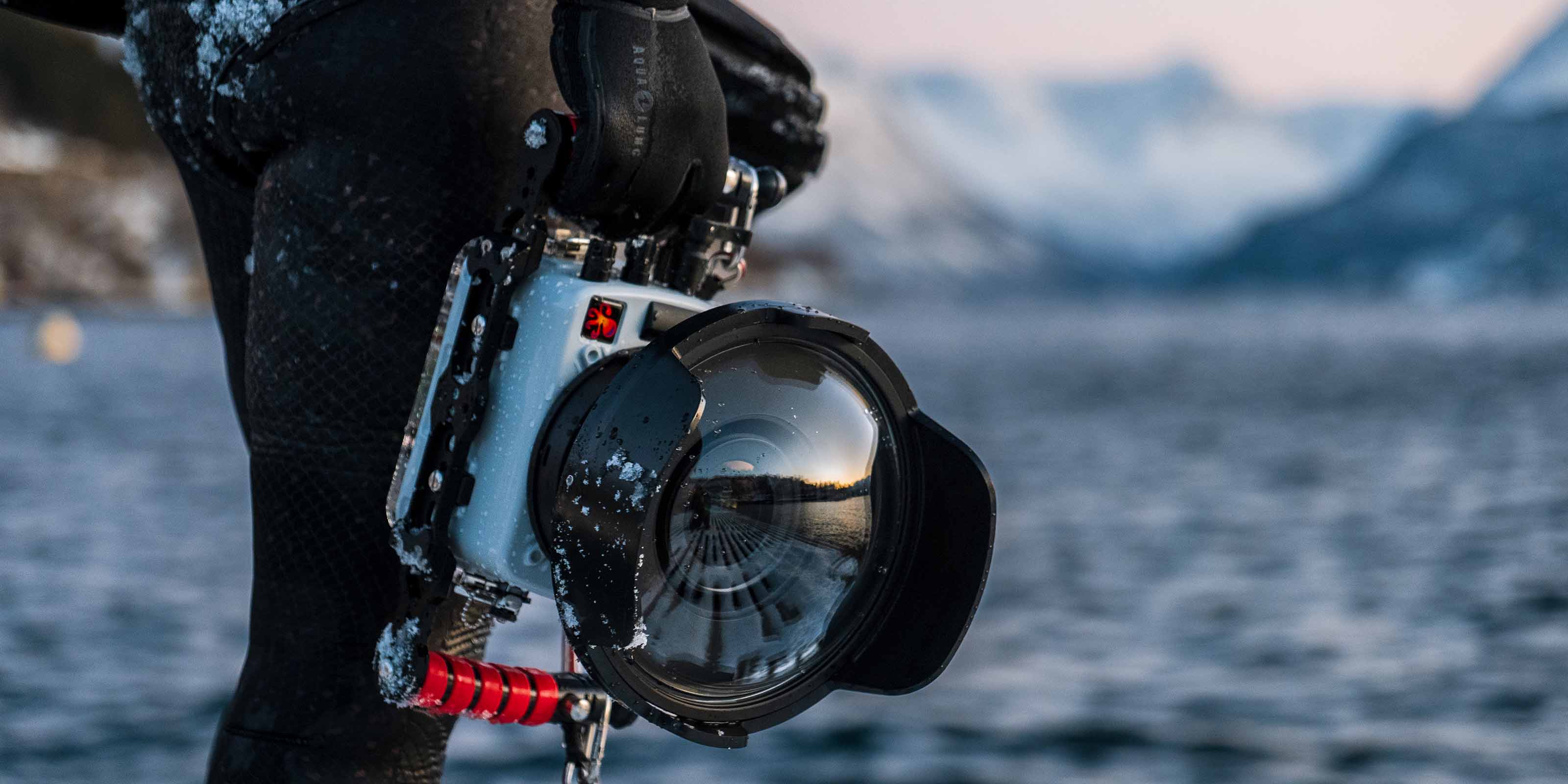
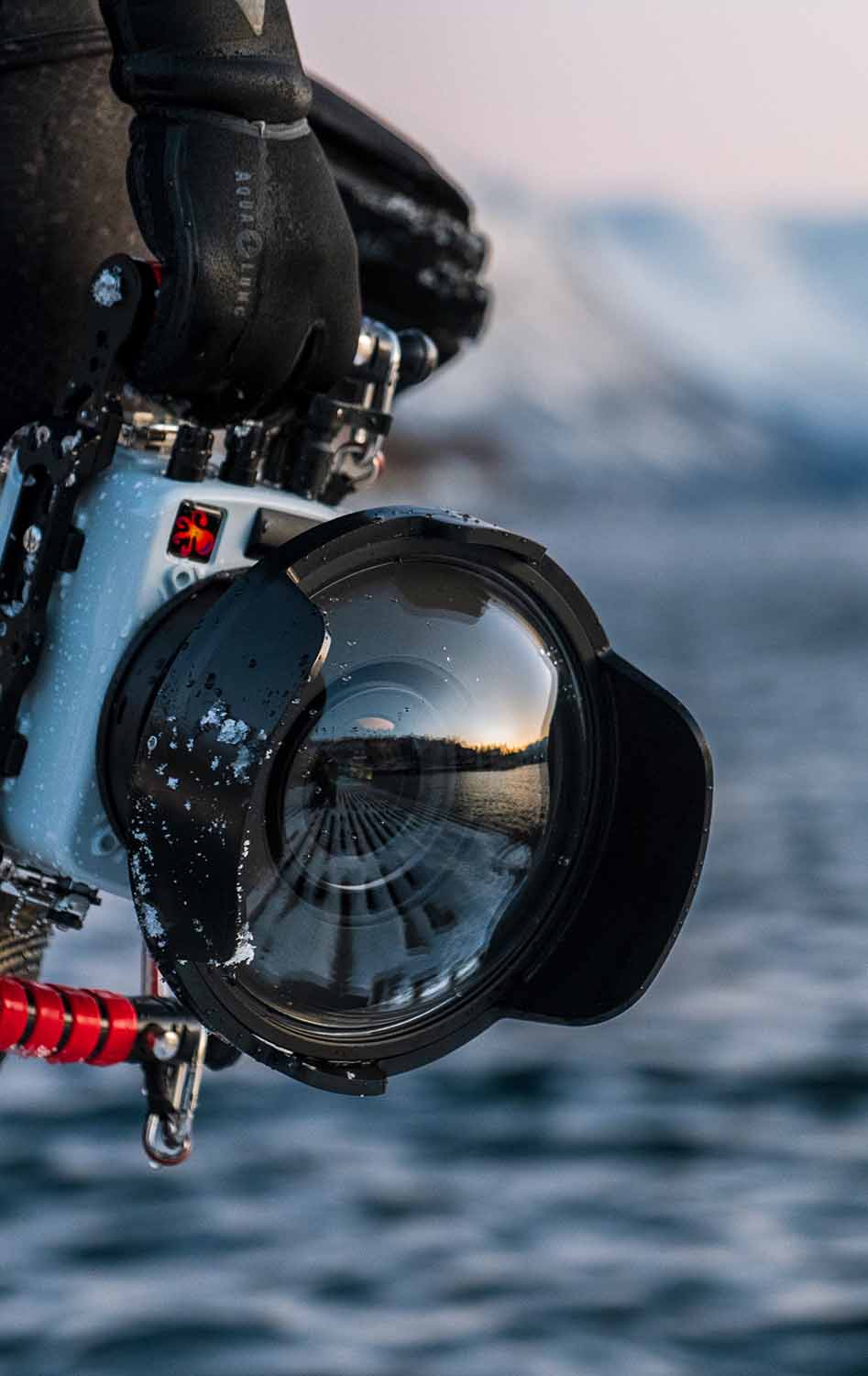
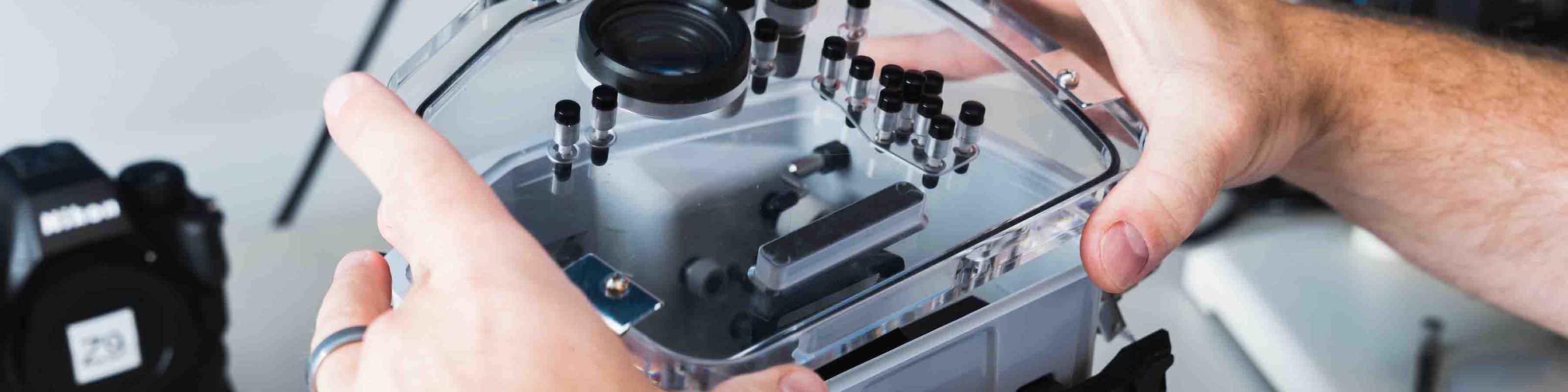
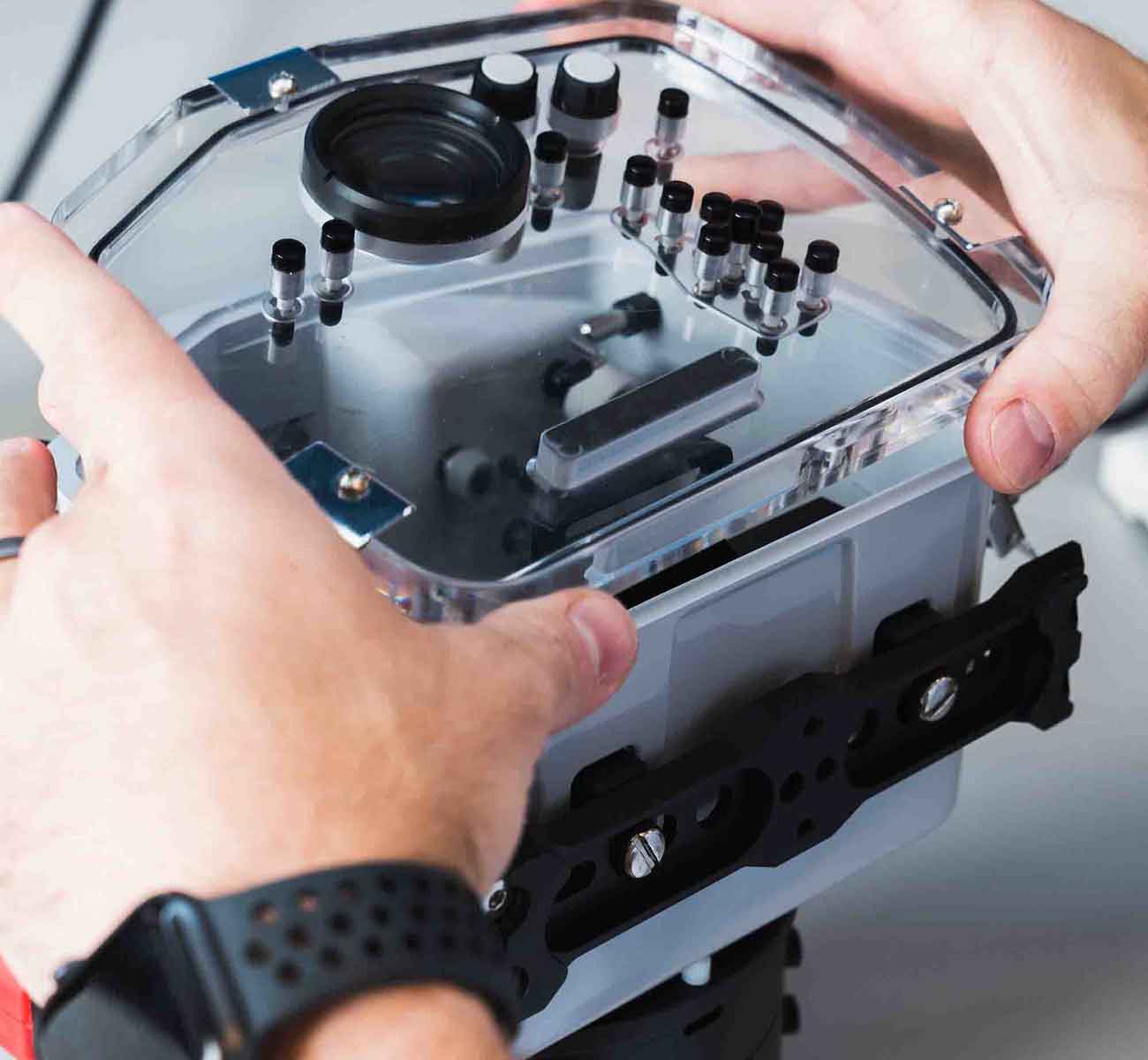
Your Camera...
From compact to full frame mirrorless, from the Arctic to Antarctica, we've got your camera covered. Find the equipment and support you need to take the plunge.
Ikelite strobes have been the only ones I found to be dependable enough for professional use in the harshest conditions on Earth.
As a working professional, I have tried and tested many other brands, Ikelite is the finest in its class bar none.
Ikelite has always offered a robust build, high power and reliability. That is very important to me in the field.
Since 1962
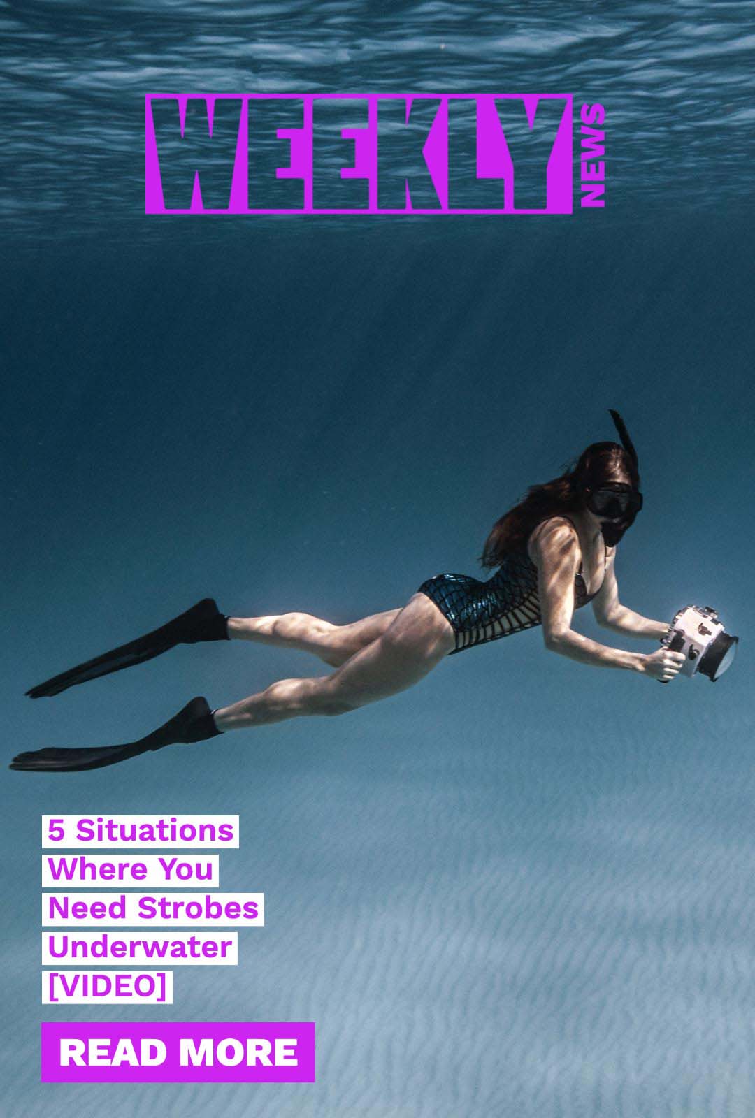
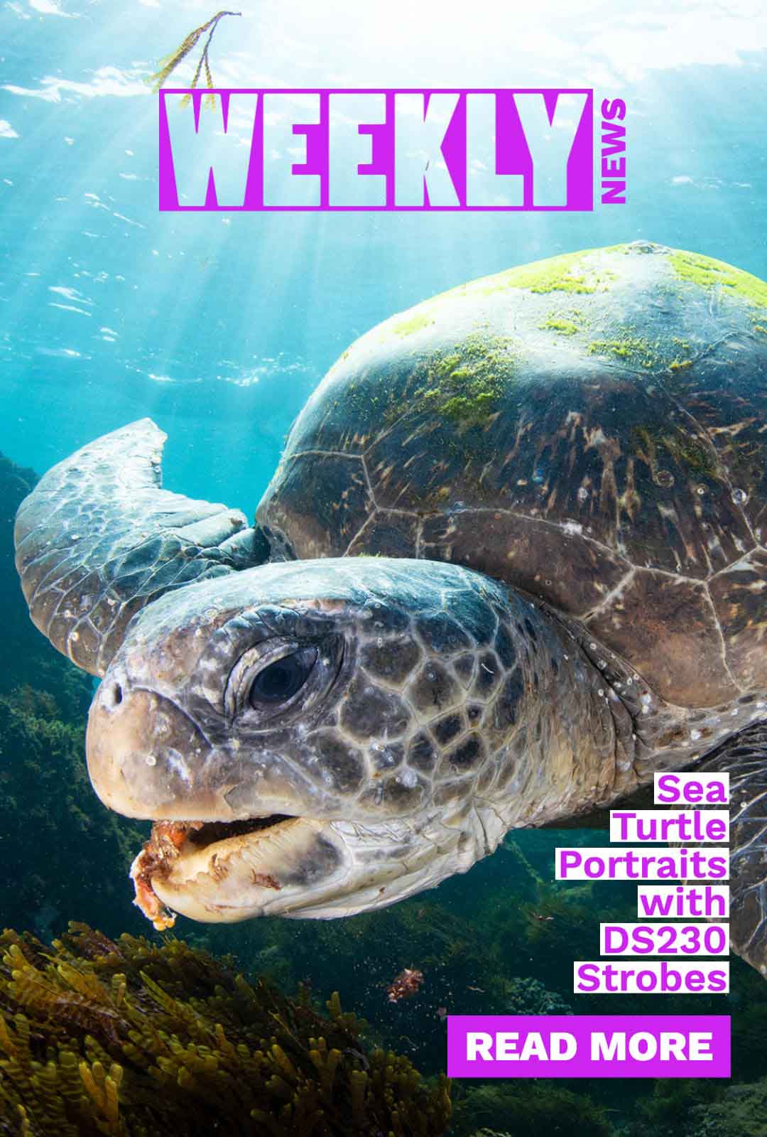
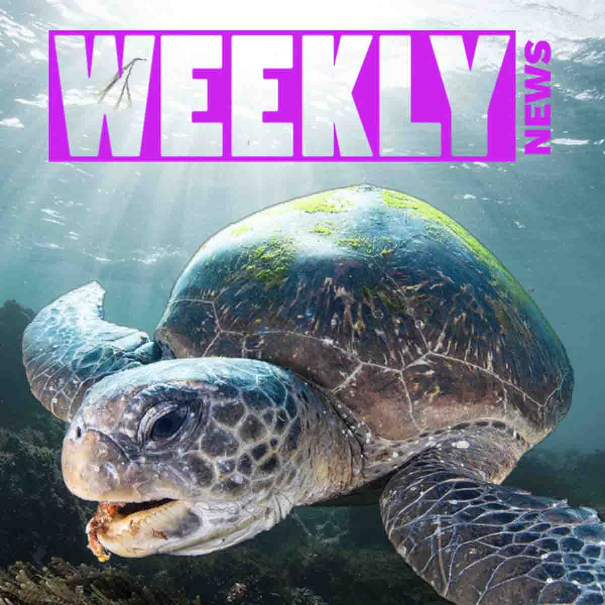
Weekly News
Our Weekly News drops every Friday morning with the latest articles and videos from underwater photography professionals around the world.
See past issuesQuick Answers
Have other questions? Contact us via email ikelite@ikelite.com or phone +1(317)923-4523.
Do you ship overseas?
We ship direct within the USA only. Our products are available in over 95 countries throgh our network of Authorized Dealers.
How long will it take to get my orders?
Most accessories ship within 1-2 business days. Most housings and lighting products are running on approximately 2-3 week delay. We do our best to get you equipment in time for your shoot. Please note on your order if you have a specific deadline.
Ready for advice?
We love to help whether it's choosing equipment, putting it together, or taking a great photo. Reach out to us today at ikelite@ikelite.com.